When installing a new power system or doing a little troubleshooting, an appropriate meter can be just the thing to make the job easier. For example, with the analog voltmeter and the digital ammeter, we were able to determine that the panel above was a little low on output. What could possibly be wrong?
There are analog meters, which you don’t see much, anymore, and the digital meters which seem to be in favor these days. There is one of each in the photo above. Below, we’ll zoom in on the analog meter for a quick briefing. It isn’t that hard, especially since they have numbers regularly spaced along the dial. I’ve recently endeavored to teach an eleven year old to tell time on an analog watch. The Timex, having 12 hours delineated was not such a problem, but a PRC200 has only 3 numbers and a Submariner hasn’t any at all. Try to explain how using a watch with no numbers is easier than looking at her cell phone! But I digress. Speaking of watches, take ’em off, along with rings or other hand jewelry. Put on some gloves for poking around in higher voltage circuits. 24v can give you a tingle if you are sweaty.
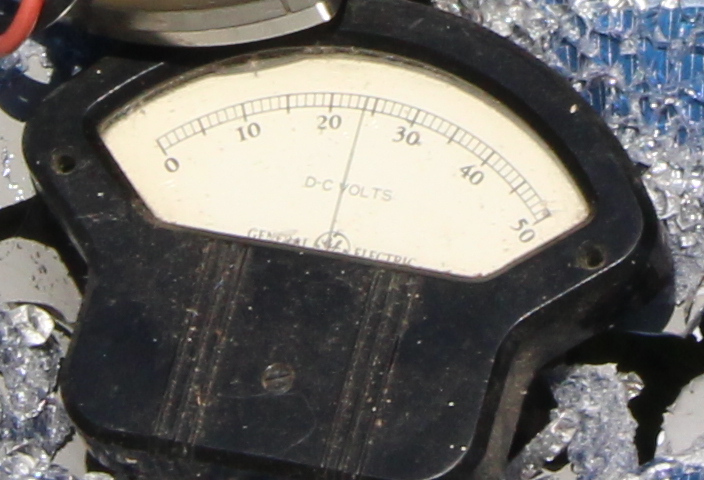
24 volts
This meter is pretty easy. There are 10 little chops between the 20 and the 30, so each chop is a volt. The needle is four chops over, so the voltage is 24.0. If it were 1/3 of a notch to the right, then you’d have 24.33 volts. A really high precision meter would have a mirrored scale so you can line up the needle with the reflection to make sure you aren’t reading high or low by looking from an angle. I grew up on this stuff, before there were digital meters, so it comes naturally to me. After dealing with the youngster and the watch, I’ll understand if it is strange to a person under 40.
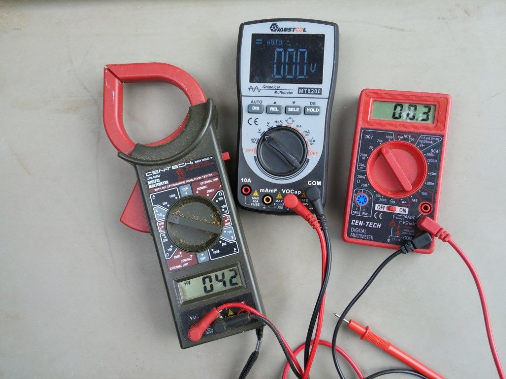
Above are some digital meters, typical of what you might use. It seems you can spend as little or as much as you like and get a useful meter. The red one you can sometimes find free, with coupon, at a certain popular tool store. As long as you remember to turn it off when not using it and don’t pull too hard on the leads, it is fine. And free. The one in the middle actually includes a digital oscilloscope! It also has better leads and will turn itself off. The one on the left is often called a clamp meter, as you pull that red trigger to open its mouth, clamp it around a wire and then read the amount of current (amps) going through the wire. Some clamp meters only work with AC, as indicated by the squiggle by the A. These are all referred to as multimeters because they have multiple uses, unlike the analog example, which only measures between 0-50 volts DC. Let’s take a closer look at the clamp meter.
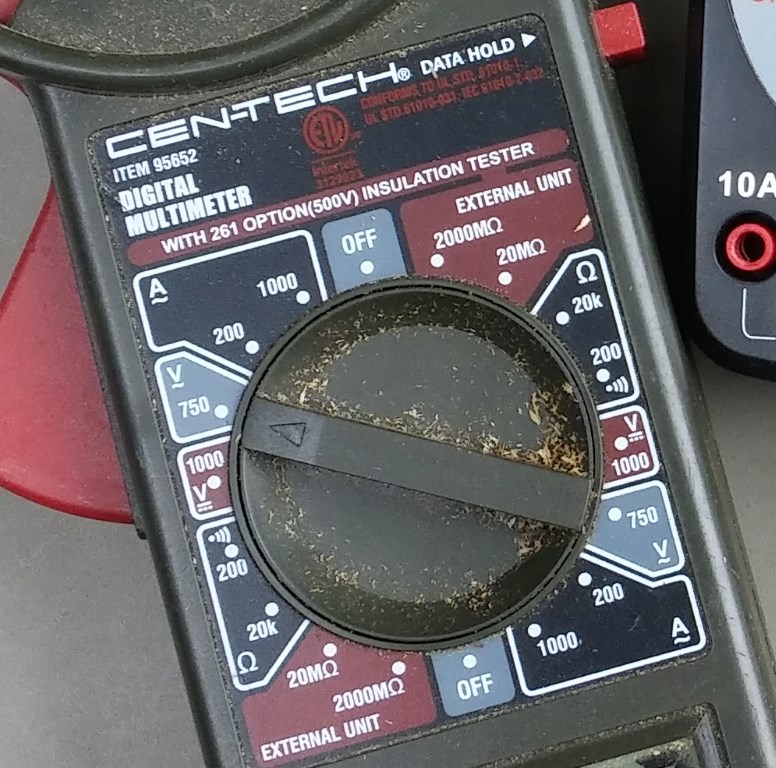
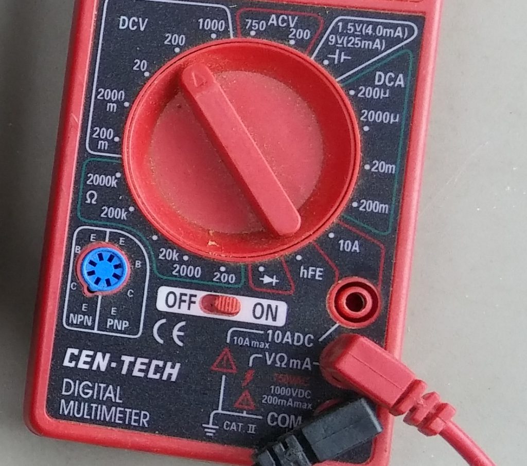
As you can tell, this particular meter lives near the bench saw. A little sawdust never hurts, but how embarrassing! Normally the arrow on the knob is pointed at the OFF to save battery. It is presently set for a range up to 750 volts AC or vac. The squiggle under the V means alternating current. The 1000V range below it has a straight solid line and a straight dashed line, indicating DC. 750 and 1000 are rather large voltages, so you will find a meter like this is not the best thing for checking batteries with any accuracy. This is best for the big voltages, like the 240vac output of your inverter or a 600 volt string input to a grid-tie inverter.
The lower left scales are for resistance. The 200 position with the funny symbol indicates that you can measure the resistance of a cable up to 200 ohms (which would be terrible) or it will beep if you have a dead short, like when testing a good cable or fuse.
Over in the lower right corner is where you check your amps with the clamp. See the A (for amps). If I clamp onto one of the big wires on my air conditioner I might see around 11 amps. You can multiply the VOLTS times the AMPS to figure WATTS. Of course, if you are drawing too many watts your circuit breaker will let you know, but by measuring when everything is right, you can make sure everything is sized properly for the job at hand. One last little feature in the upper right corner of the photo is the HOLD button. If you have to put the meter into a position where you can’t read it to clamp onto a wire, you can press the red button to hold the display until you can pull it back to read it.
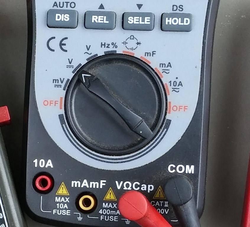
The meter in the middle has a lot more precision and it has automatic ranging, so you just set it to AC or DC or whatever and it figures out if you are measuring a volt, 100v or even more and displays it in the proper context. It even has a built in frequency counter (Hz) that can tell you if your inverter is putting out 50Hz or 60Hz. The inverter can be set wrong and it can make a difference! The oscilloscope function is not great, but it can tell you if a power output is a sinewave or a modified sine wave.
The main reason I wanted to show you this one, though, is the sockets where the meter leads plug in. This meter is pretty typical in that respect. The black lead always lives in the COM hole and the red normally lives in the V socket. To measure current, you set the dial to the appropriate position and move the red lead to the 10 amp or ma position. Don’t mess this up! When set up for measuring current, you usually use the 10 amp scale for solar and you take the cable off the battery. If you pull the positive cable off the battery, put the red lead on the positive (+) battery terminal and the black lead to the wire you took off the battery. You can now measure the current going through the circuit. Note that the meter at the top of the page is set up for current and is reading nearly an amp of current.
You can use this mode to test a solar panel by setting the 10amp mode and poking the probes into the connectors on the solar panel. If the labels on the back says you should have a short circuit current of 7.4 amps, then that is about what you should expect if you check the current of a CLEAN module pointed straight at the sun. In fact, checking both the current AND the voltage is a good idea.
Here’s what you have to watch out for, though. When you are through checking amps, DON’T just turn the meter off and stuff it back into the tool box. You usually test voltage, or most folks do. If it is set up for AMPS and you put the leads across the battery you are going to be very disappointed with yourself, because at the very least you will blow a fuse in there. You might also burn the leads or a bit of circuit board. Not fun.
Let’s see if there is anything interesting about the free red meter.
You can see that this one is not auto-ranging. Like the clamp meter, the AC range is pretty high, but that’s ok. There are lots of choices on the DC range. If you have a 12v system, select 20, because the battery may get up to 15 when charging. For a 24 or 48v system use the 200v range. This one does not have a beeper in it, so select the 200 resistance setting or maybe the pointy diode symbol to check a fuse. Like the other meter, you move the red lead to the 10ADC socket to test real amps and don’t forget to put it back when finished. You probably won’t need any of the rest of it. If you do, you already know how to use the meter, I suspect. DON’T leave a cheap meter on when not in use. Of course it runs down the battery, but on some it will also burn out the display owing to electrolysis. Who knew?
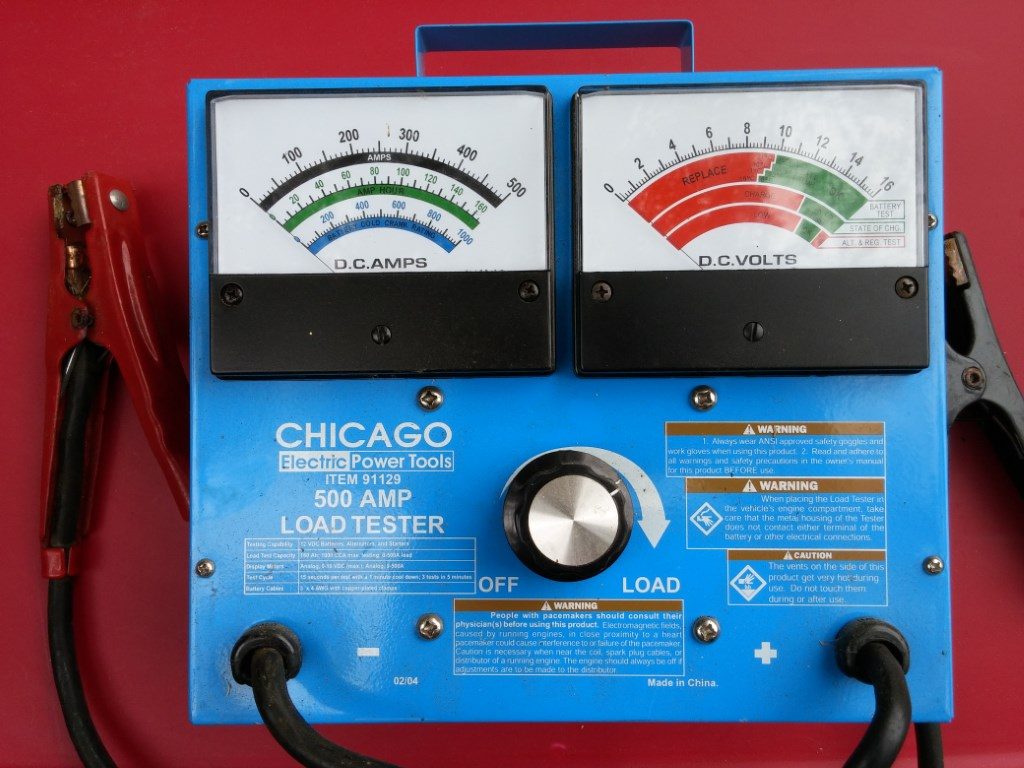
Here is a handy meter to have if you have batteries. (above) Yeah, it is analog, but I like analog. With one of these, you turn the big knob counterclockwise until it feels loose. This is primarily a 12 volt tester, but if you are using 6 or 8v batteries you can either interpolate or put the 6v batteries in pairs for the test. Come to think of it, you’ll just cause trouble if you don’t keep it down to 6 or 8 volts. We’ll start off with a marine deep cycle battery as a 12 volt example and just scale everything down for the lower voltage batteries. If it is your meter, you can make your 6v marks with a Sharpy. Disconnect the batteries from the charging and load circuits and clamp the red clamp on the positive terminal and the black onto the negative. Watch the terminals when you increase the current. A bad connection can get real hot in a hurry with hundreds of amps involved!

If it is a fresh 12v battery you should get a bit over 12 volts, maybe even over 13. Anywhere in that middle green zone on the right is fine. Nothing should happen on the left meter until you crank the knob clockwise. You will tighten it until the needle falls down into that area where the red and green show a stair step. Guess the temperature and choose your notch. This is really loading the battery. To get a good estimate of capacity, you now look over at the left meter.

This unit is really set up for testing something the size of a car battery, so two T105 or Sun230 or GC2 batteries in series are going to slam the needle off scale to the right because they should indicate over 200 amp-hours and the scale only goes to 160. If the needle slams to the left you hooked your cables up backwards and you just broke something.
Anyway, for a trolling battery, you should see something on the order of 80-120 on the green amp-hour scale and you should see it hold fairly steady for about 15 seconds or until the timer beeps. If testing a 6 volt battery, turn the knob until the VOLTS needle is in the 4-5 range, depending on temperature and roughly double what you see on the left meter. The real key here is that the amps should drop rather slowly on a good battery and they will go quickly on a bad one or one that is badly sulfated. If you ignore the timer and leave it connected the tester will begin to smell bad and that can’t be good. It never is. If testing a number of batteries, take your time and let the giant resistor cool down a bit.
That may sound complex or tedious, but really it isn’t once you’ve tested a few batteries. Read the manual for all of these meters for the fine points of use and care.
Quick tips on what to do with your meter? Check your solar panels you just got in or if your system is acting up. Specs for volts and amps should be on a label on the back of the panel. If not, you can Google just about any panel data sheet.
Check a fuse, circuit breaker, cable or switch for continuity.
Check the output voltage and current of your inverter or charge controllers. Most have built-in metering to some degree, these days, but sometimes a second opinion can help.
Test a battery.
Make sure the cables are the right polarity before connecting panels or batteries to other expensive stuff!
Well that should be enough to get you started. Have fun with your new meter. –Neal