Let’s build some cables
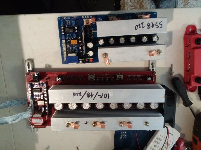
I told you the other day I had reached the limits of what my homebrew 5500 watt inverter could do. I had a 10kw driver module to install, but it was bigger and was going to need some more cables.
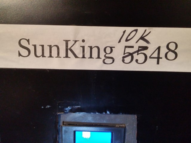
One night I switched the house to grid, ran a power cord from the Sun King for lights and I shut down the inverter for a recon. What I found was that I could use what was in there, but I need to add some cables because a 10kw inverter eats lots more amps than a 5kw unit. I made measurements and notes and buttoned things back up a threw all the switches. Next day I built cables.
John likes me to talk about the basics, so here was a perfect opportunity. If I were building this inverter from scratch, I would use four parallel #6 cables because they would add up to plenty of current and wire that is easy to bend.
I promise we’ll eventually get to the fun stuff, but we gotta do the book learnin’ stuff first.
Let’s start with the cable itself. I’m talking power cables here, for high current. These are cables you might use to join batteries or to go from batteries to inverters. How big do you need? Well, I want to run a 10kw inverter on 48 volts, so it is easy to find out how many amps. 10,000/48= a bit over 200 amps. NOW the question is what size cable do I need?
Look on the internet and you can find ampacity for various gauges of copper wire. I don’t like most of these charts because they relate more to how many amps you can get through the wire without melting the insulation or starting a fire than how much is safe, practical and has little resistance. I have a memory trick I use to come up with numbers I like. I can remember the common household gauges of 12 and 14. You use 12 on 20 amp circuits and 14 on 15 amp circuits in the house, though 14 gauge is banned in some places.
Wires and cables are typically even numbered and if you go down two even steps, you double the capacity. So going from 14 to 10 you double from 15 to 30 amps and from 10 ga. to 6 ga. you double it again to 60 amps. Some charts will say 6ga. will carry a lot more and it will, but it will get hot and drop some volts. If I were making a long cable, I would run less than 60 amps in 6 ga. cable. It boils down to USE A BIG ENOUGH CABLE. Or enough little ones.
But wait! Why am I building 60 amp cables when I need 200 amps? If I went with 4 60 amp cables, filling up all the terminals, I’d be good for 240 amps. No problem.
I’m not going to make it that easy, because the negative line already has a good 2 gauge cable. That’s two steps down from #6, so we double again. That’s a 120 amp cable. Adding my two 60s and we have plenty of amps.
Regardless of whether any of that sank in, we are going to build 6 gauge cables today, because that’s what I need for my project. My favorite cable for this is marine cable. It is fairly tough, very finely stranded and flexible and every strand is tinned. In some cases you might be required to use cable that is UL listed for solar applications. If you are wiring inside your inverter or making cables for your golf car batteries, then use what works for you.
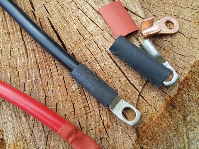
What do we need? Wires, terminals and tools. I have a roll each of black and red #6 cable I’d bought for something else. Having both black and red makes it pretty obvious which is for positive and negative. Here’s a tip, bolt cutters make great cutters if you have a set just for cables. You won’t be happy if you cut the bolt first.
The inverter module came with some terminals that have foldover tabs. They are not my favorite, but they were free and they fit the screws. I also have some heavy duty tinned terminals, too. Terminals, by the way, are sold according to wire size and stud size. Putting #6 wire in a terminal made for 00 gauge wire is not a good plan. Match your terminals to your cables. It’ll mean having more terminals in the bin, but will make for better work.
You’ll need some pliers to bend over the tabs on the copper terminals, but don’t think that makes you done.
You need a crimper tool. Some look like bolt cutters, except they crimp instead of cut. I have a couple that are like little presses that hold the terminal in place while you give it a couple of whacks with a big hammer.
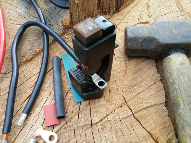
The tool I use works best when it is sitting on an anvil. My shed anvil has gone missing. There’s one over near the barn, but that’s a long way and it is heavy. Today, we are substituting the stump of an oak tree that dared to extend a limb over my solar array. Take that!
An anvil works better. Last time I lost an anvil I found it with a bush hog. That wasn’t good.
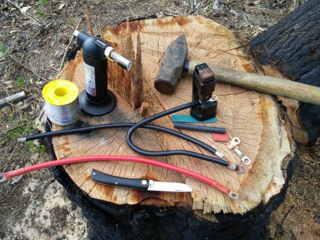
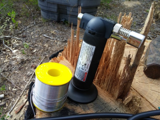
Back to tools, you’ll need a sharp knife. Keep it simple. I use a sodbuster and a lot of electricians use Barlows. A butane mini torch is very helpful for soldering. You’ll need a roll of solder, too. I like old fashion 60/40 rosin core. Never, never ever use acid core or stuff from the plumbing department. A good collection of shrink tubing is very nice to have for professional results.
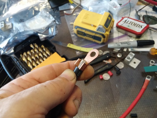
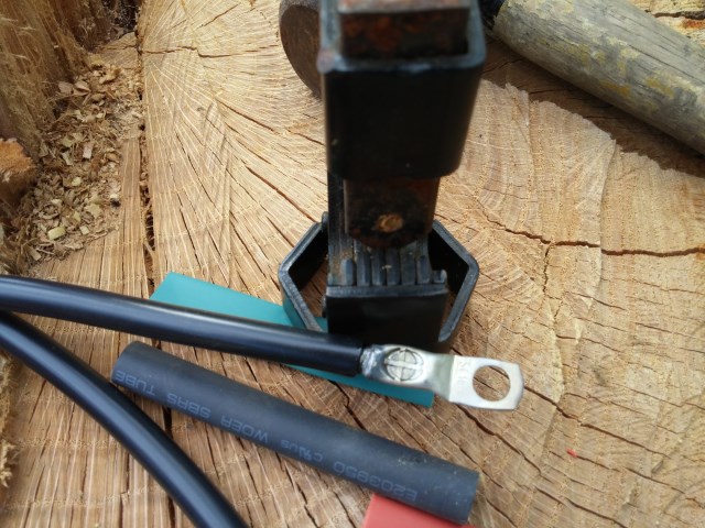
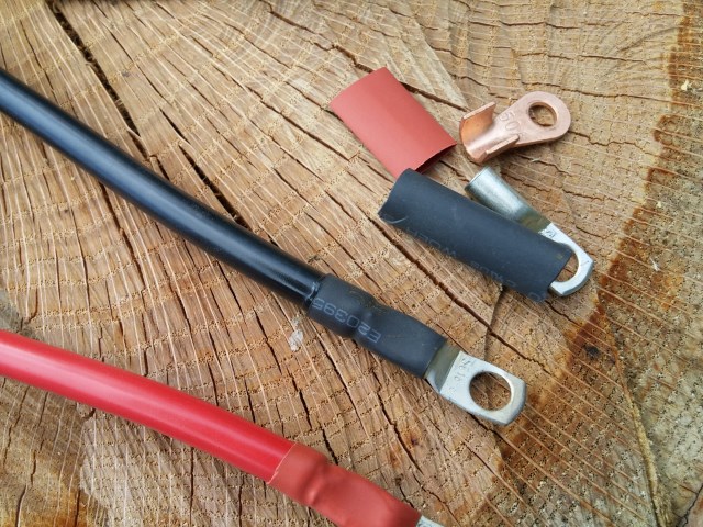
Here we go, now. Determine how far back you need to strip off the insulation. Use the knife to go around gently, getting through the insulation without cutting the wire strands. For the open terminals, take pliers and bend over the tabs the best you can to hold it in place. On the tube terminal, just slip the cable in, making sure you get all the strands in.
Next, put your wire and terminal in the crimper and do the deed. In the kind I use, a “+” sign is embossed to show you got a good crimp. Some people are happy to stop here, but we are going to solder, too.
To solder, you’ll need your mini torch. A jet lighter will work on these smaller cables, too. Put the flame on the terminal, with the overshoot going away from the insulation.
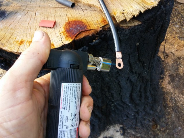
On an open terminal, like our copper example, poke at the cable to see if it is ready to melt solder. Don’t put the solder in the flame. It will melt and fall into your shoes. On the closed tube terminal, poke the solder in at the gap between the insulation and the metal. When it begins to melt, run it on in. When it begins to puddle you have enough. A slight shake will get rid of excess. Let the cable cool before the next step. Warning: If you are making really big cables like 00 and 4/0 gauge, it WILL get hot.
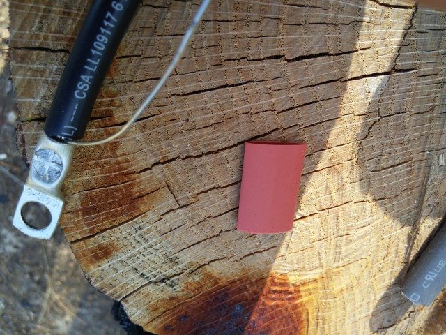
Shrink tube comes in all sizes and types. There is some really thin cheap stuff on ebay and you should avoid it. The best and most expensive is usually referred to as marine type. It has a melty inner lining that seals up both ends. This is great on boats and around battery acid.
I like to keep red and black tubing to help denote polarity. Sometimes I only have black cable and the colored ends help keep things straight. Ideally, you own a heat gun to shrink the tubing. A hair dryer can work in a pinch. If you are careful, the mini torch works, too. Just back off 3 or 4 inches and keep the flame moving. You can screw it up in an instant.
One other handy trick is to buy CLEAR shrink tube. You type/print a message on paper, like “Main Inverter Cable, Positive”, slip the clear tubing over the cable and slip the message under the tubing. When shrunk, you have a permanent ID for that cable.
So there we have ’em, the new cables to go into the inverter project. I will eventually double up the 2/0 cable going from battery to inverter. The ones that are there are adequate, but I will have less resistance and voltage drop. Why double cable instead of bigger? First, I don’t do 4/0 cable. I can get it for the same price as 2/0, but I just don’t like it. Second, I have the 2/0 cable and maintain a supply of terminals.
In case you are wondering how the inverter project turned out, it went splendidly.
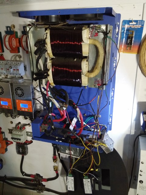
It fired right up without any complaints. I still have a few loose ends on changes to fans and control cables, but it is running and we’ve had no more overloads.